115v Pool Pump Timer Wiring Diagram
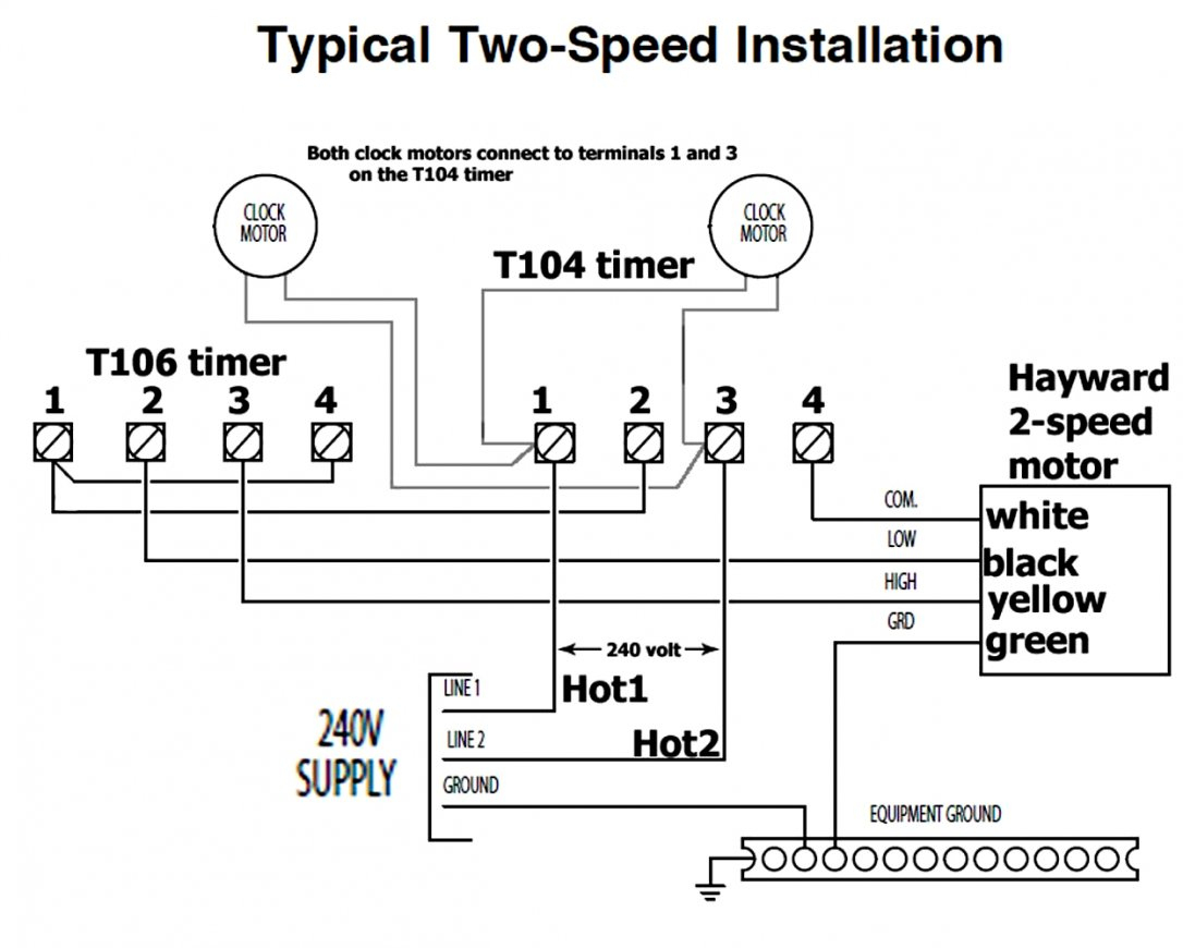
Intermatic is the most common timer used on pools. I am wiring my 2 speed pump 230v for my pool through 2 timers.
Hayward Super Pump 115v Wiring Diagram
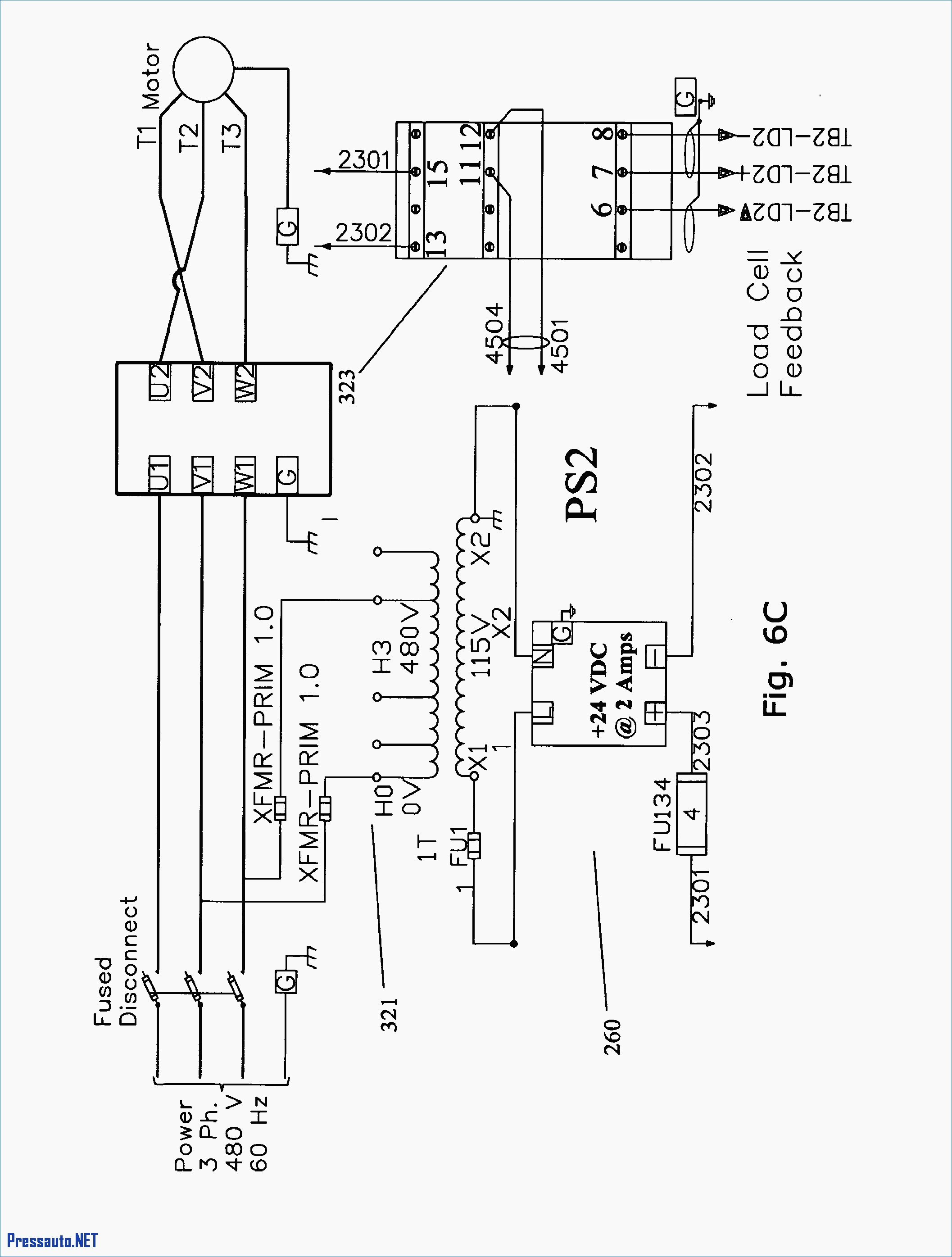
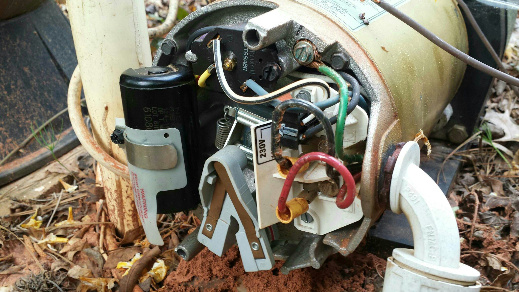
Most pool pumps use a 220 volt capacitor start induction run csi electric motor wired directly to a pool timer through a flexible conduit or whip.

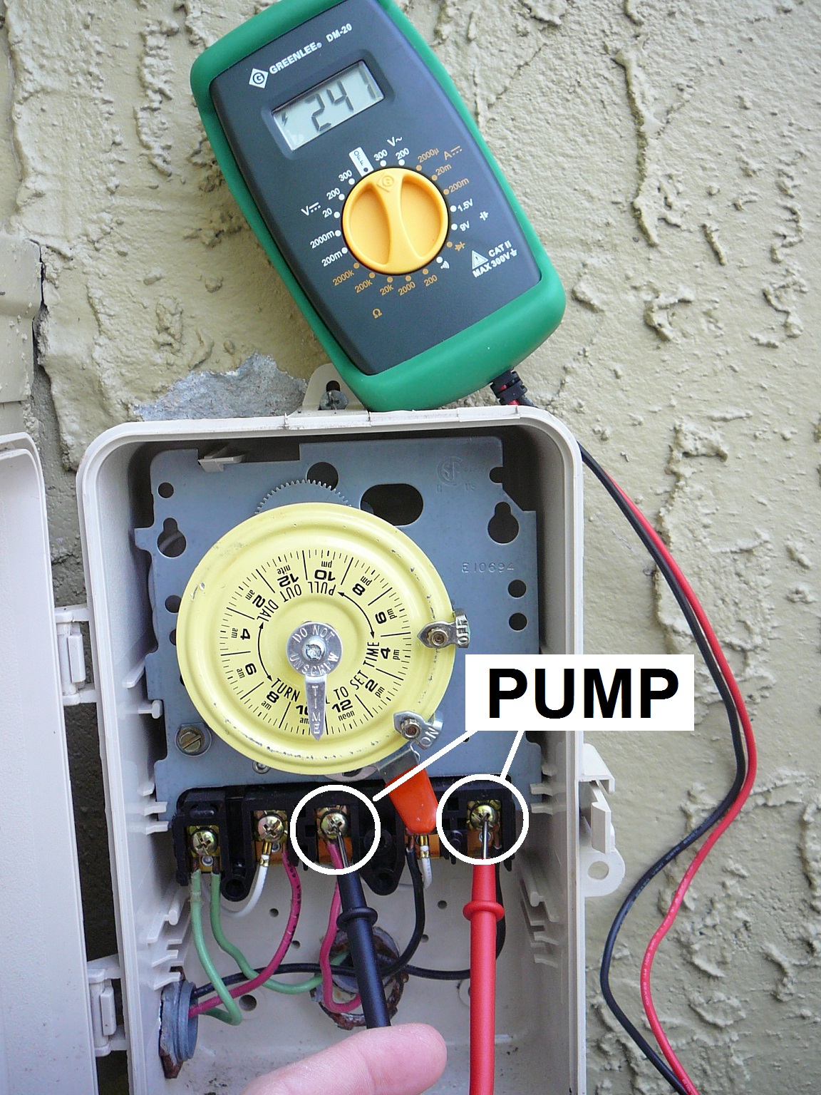
115v pool pump timer wiring diagram. From the breaker, it goes to the first timer. Equipment pad wiring, basic info on how pumps and other pool electrical loads are pool perfect with phosfree intermatic pool pump timer intermatic pe pool if you want to switch it to v, follow the label diagram to reverse the voltage. Here are a number of highest rated timer switch wiring diagram pictures upon internet.
I am rewiring my pool to replace the timers and add freezing controls. My pump doesn't work, so caveat emptor. Wiring diagram comes with several easy to adhere to wiring diagram instructions.
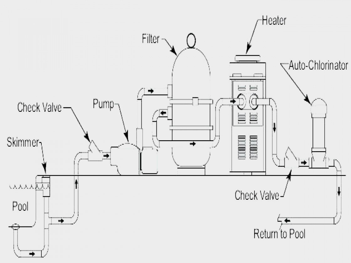
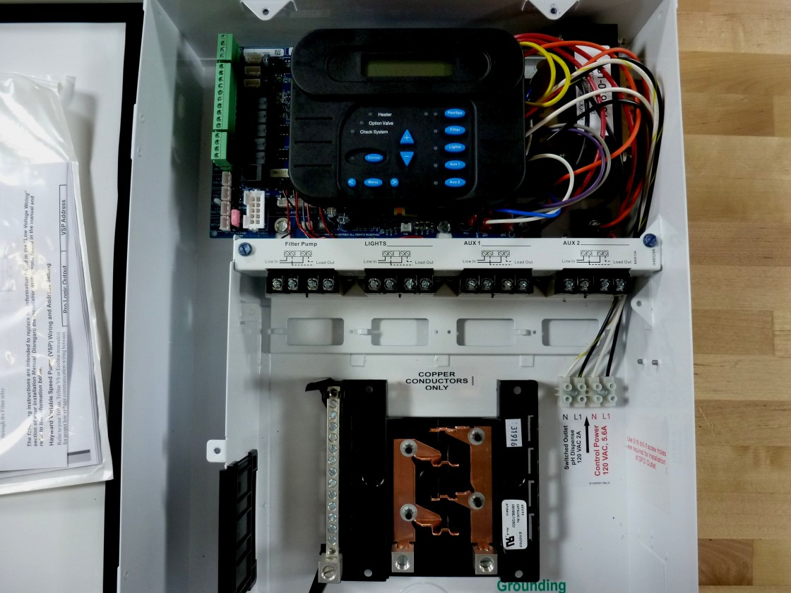
Ge timers may be used to control up to 9 on/off cycles per day (or any other pool equipment) or control speed changing for multiple speed pumps. Hayward builds high performance quality and reliability into every heat pump with a titanium heat exchanger quiet operation and easy installation. With this sort of an illustrative guide, you are going to be capable of troubleshoot, avoid, and full your assignments with ease.
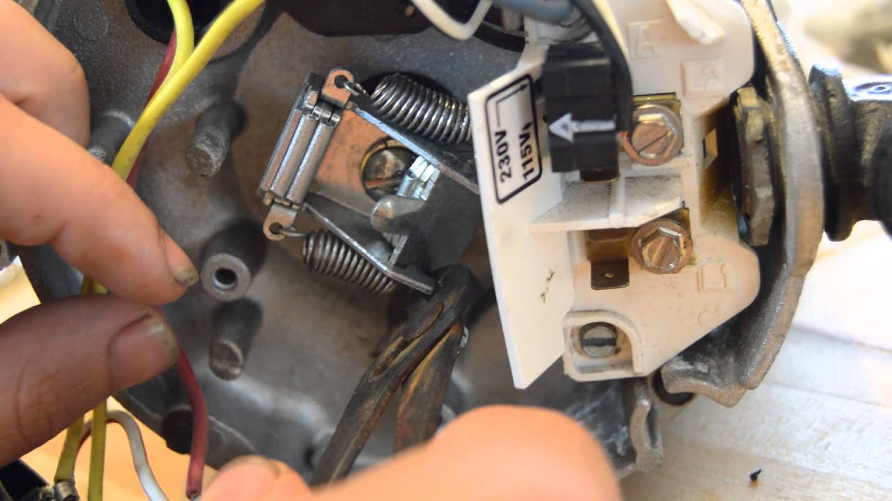
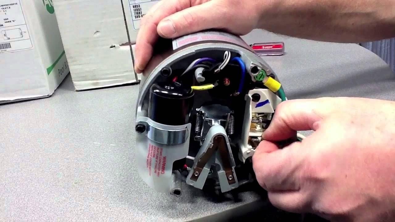
I used this vid to see how to rewire my pump for 115: It’s intended to help each of the typical person in building a correct program. Seal installation see parts diagram on page 9 of this manual for pump.
Page 14 english polaris pb if you are wiring for v, the three wires to the pool pump will be black, white and green. I have a new switch( 240v 30amp double pole single throw), but i do not know how to connect the wires. Hi, i am utterly confused about pool pump timers.
How to convert an inground pool pump motor from 115v to 230v youtube pool pump hayward pool pool supplies. I'd say about 14,500 gallons. Wiring a pool pump and switch [ 1 answers ] i am trying to wire a new switch to my pool pump it is a 230 volt.
The is no designation on the switch as to where which wire should go. Maybe experienced people just know what that means. Ge pool pump timers are the best value in swimming pool timers and time clocks.
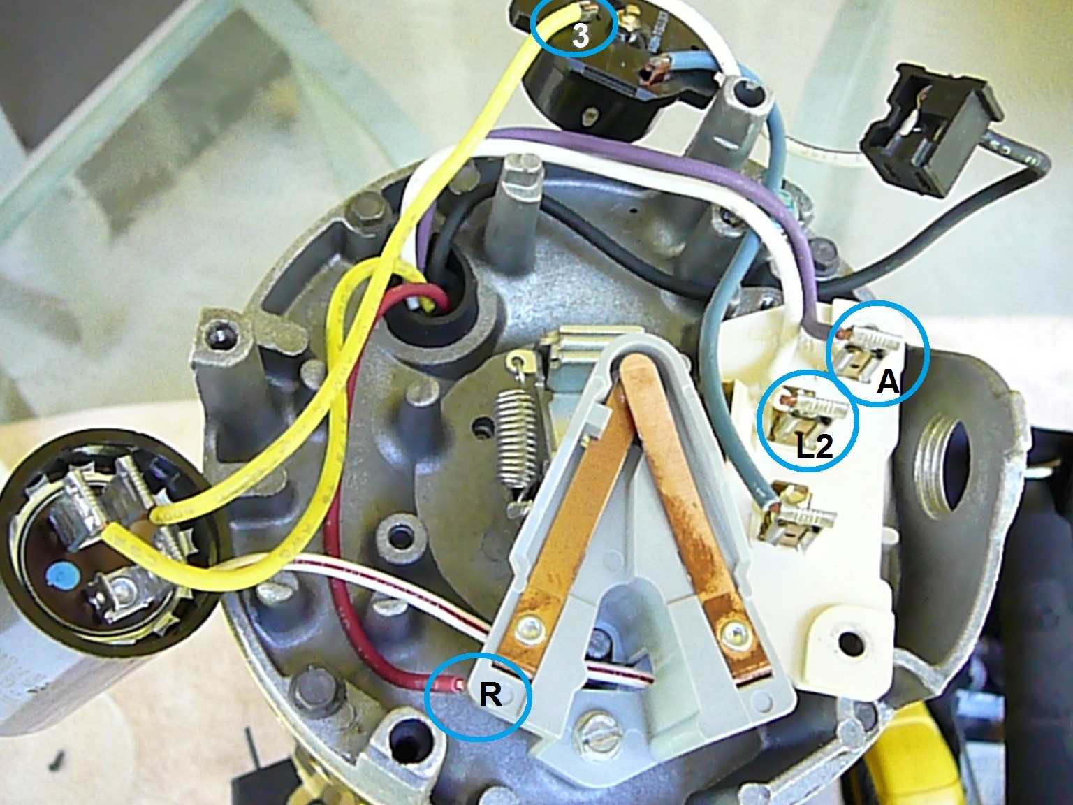
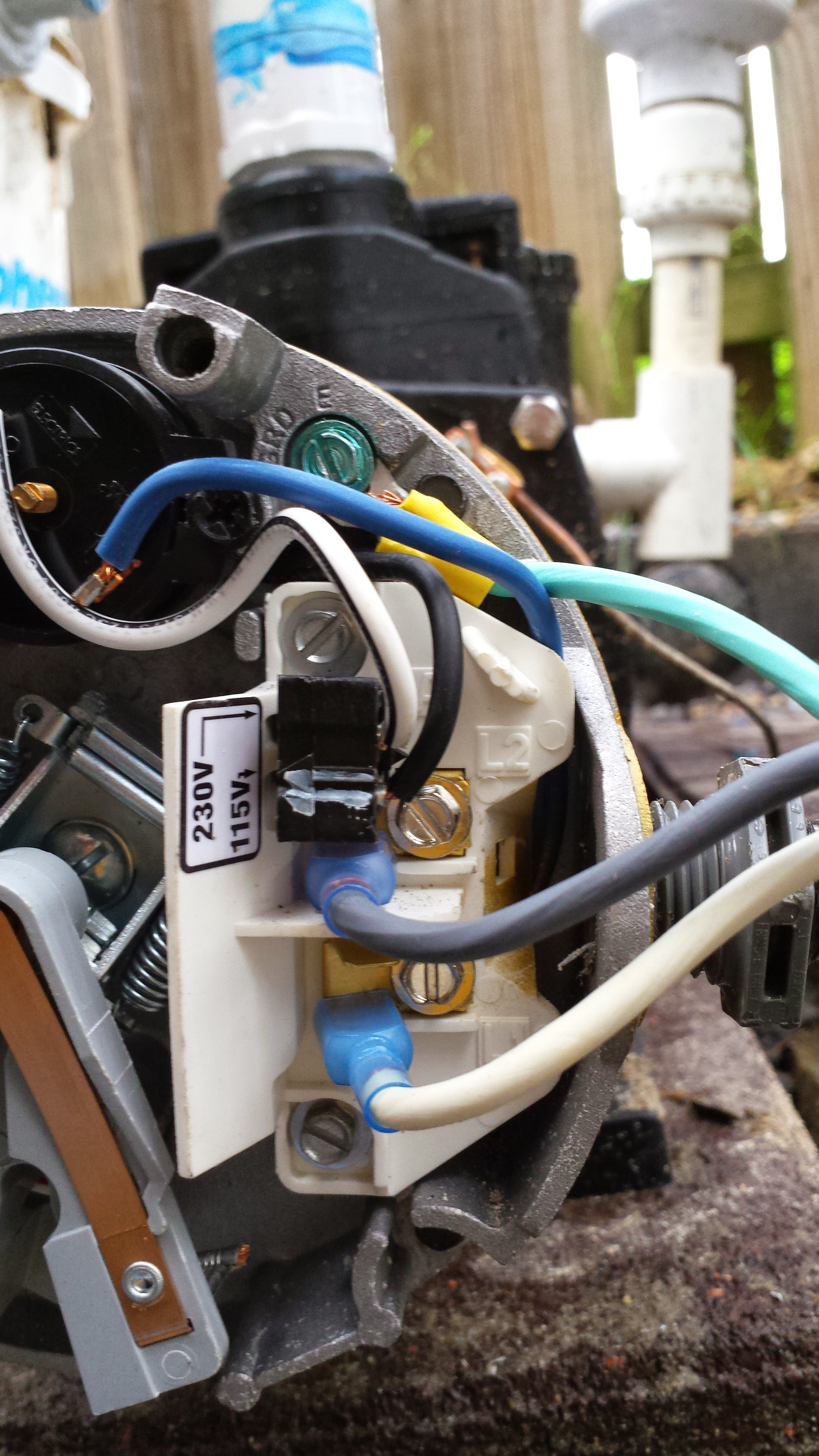
Attach the green wire under the ground screw (gnd). Wire whisperflo & similar pumps for 115v. Hayward super ii pool pump wiring diagram wiring schematics diagram hayward super pump wiring diagram 230v.
Not just will it assist you to achieve. When the timer it turned on, the black (ie common. These guidelines will likely be easy to understand and use.
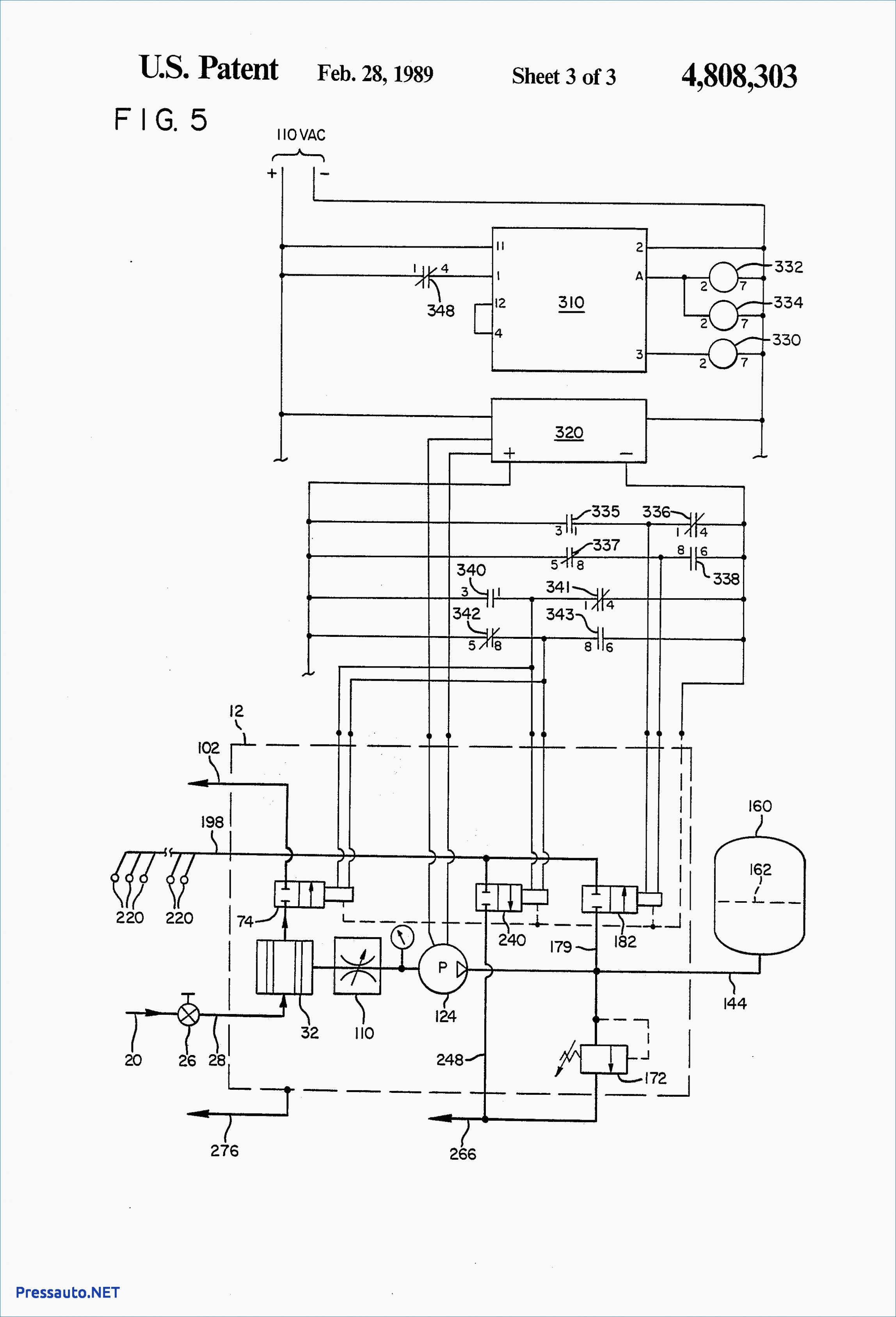
Its submitted by giving out in the best field. To configure the internal wiring of the pump motor requirements for the correct voltage, refer to the diagram on the the polaris booster pump requires a dedicated motor data plate. Submersible pump control box wiring diagram for 3 wire single phase submersible pump electrical circuit diagram submersible it.
115v breaker wiring diagram this service is very simple to wire just follow the color coding for the connections if marked and use the correct size wire the black wire or hot it is connected to the breaker and to the brass colored screw if marked some receptacles do not the above 30 amp 120 volt service will supply 3 600 watts , If you are wiring for 115v, the three wires to the pool pump will be black, white and green. A wiring diagram is a type of schematic which utilizes abstract pictorial signs to reveal all the interconnections of components in a system.
I have 220v service at the pool (not sure why it was wired 110v anyway), so the question is: Aboveground pool pumps are often v only, wired with a power cord, and.may 22, · watch as joseph and lucas show. February 20, 2021 · wiring diagram.
With such an illustrative manual, you are going to have the ability to troubleshoot, prevent, and complete your tasks easily. What is the benefit, if any, of 220v vs. Century's premium efficiency motor, the first motor with an integrated timer, addresses the challenge many pool.
An intermatic timer switch saves electricity when it turns a water heater off at night and when it limits the amount of time a pool s filtration system runs. We have an above ground 24ft round, 54 inch deep pool. Hayward super pump wiring diagram 115v there should be a diagram on the inside of the wiring compartment cover if you are wiring for v the three wires to the pool pump will be.
5/8 diameter threaded stainless steel shaft; Attach the white wire (0 v) to terminal 3 of line 2 (l2). This state of the art time clock has many more useful features than mechanical time clocks.
Power in, power out and your neutral line. Pool pumps are wired to run on either 230v or 115v. The 1hp pump, polaris and chlorine generator are currently wired for 110v.
1 to turn on the motor the other to switch between high and low. Attach the black (115 v) wire to terminal 1 of line 1 (l1). 110v for the pump, polaris and chlorine generator?
Timer wiring diagram currently available at philippapearson co uk wiring diagram free for you within intermatic intermatic photocell wiring diagram simple diagrams and timer 110v pool timer wiring diagram data in intermatic how, i m using a fiberstars wpc 2 wireless pool control unit with a timer that can be wired for either 110v or 220v with a. Each part should be set and connected with different parts in particular manner. In your wiring diagram, and in mine, they make it ambiguous by referring to the power wires simply as line 1 and line 2.
I have a red a white and a black wire and a bare wire. Get more information on the worlds leading energy efficient pool pump technology in a downloadable pdf brochure. We admit this kind of timer switch wiring diagram graphic could possibly be the most trending topic when we ration it in google gain or.
Otherwise, the structure won’t function as it should be. A hayward 1 hp, 115v, 13.8 amp pump and hayword sand filter. Attach the white 115 v wire to terminal 1 of.
Hayward Super Pump Wiring Diagram 115V Wiring Diagram
Hayward Super Pump 115v Wiring Diagram
115v Pool Pump Timer Wiring Diagram Mardiniagusk
Hayward Super Pump Wiring Diagram 115v Free Wiring Diagram

Hayward Super Pump Wiring Diagram 115v Free Wiring Diagram

Hayward Super Pump Wiring Diagram 115V Cadician's Blog
Hayward Super Pump Wiring Diagram 115V Cadician's Blog
Hayward Super Pump 115v Wiring Diagram
conseiller lequel choisir top 5 Schéma de câblage Hayward Super Pump 115v France Detailing

Hayward Super Pump Wiring Diagram 115v
Hayward Super Pump Wiring Diagram 115V Cadician's Blog

Hayward Super Pump Wiring Diagram 115v Free Wiring Diagram

Hayward Super Pump Wiring Diagram 115V Wiring Diagram
Century Pump Wiring Diagram Wiring Diagram 220V Pool Pump Wiring Diagram Cadician's Blog
Hayward Super Pump Wiring Diagram 115v

How To Convert An Inground Pool Pump Motor From 115V To 230V Youtube Hayward Super Pump
Grasslin Timer Wiring Diagram 36

Hayward Super Pump Wiring Diagram 115V Cadician's Blog
Hayward Super Pump Wiring Diagram 115v Free Wiring Diagram
