Cooper Lighting Wiring Diagram
Step 3 thread fixture wires through cover plate gasket. Cooper lighting control wiring diagram pdf.
Cooper Light Switch Wiring Diagram Circuit Diagram Images
A wiring diagram is a simplified conventional pictorial depiction of an electrical circuit.

Cooper lighting wiring diagram. Mini cooper s r56 wiring diagram. Cooper wiring devices will replace or repair the motion. Modular wiring systems because modular wiring systems are basically “plug & play,” you.
Step 2 match up screw holes on the cover plate with the junction box screw holes. Cooper lighting metalux the problem i am running into is with the wiring. In which i done all the connection.
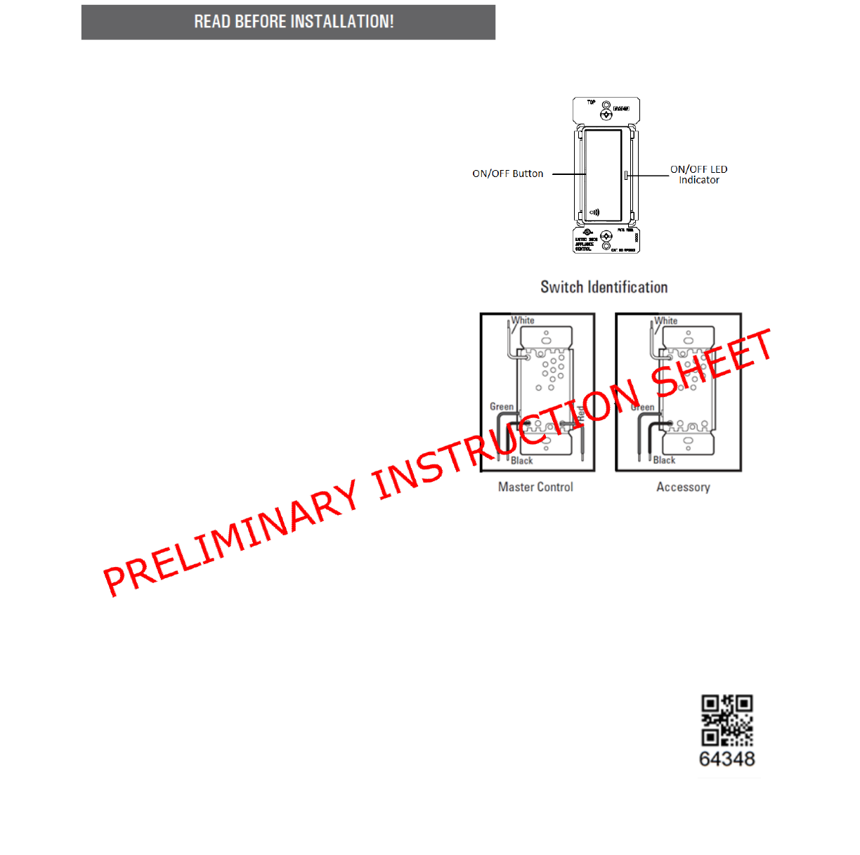
After driving for 20 mins transmission suddenly doesn't like to stay in 4th gear and jump to 5th gear right the way ( manual mode) limp home mode is triggered. Available in black (ms34) and white (ms34w) spec sheets. After installing the test button / indicator light, mark it with the appropriate label.
Welcome to our support center. Two 150w (maximum) par bulbs sold separately. My car only has 110k miles, transmission fluid has just replaced.
If a room is wired for two circuits using two separate hot leads. R56 retrofit oem bixenon north american motoring. Cooper (r56) ll (n12) > mini workshop manuals > maintenance > fuses and circuit breakers > fuse block > component information > diagrams.classic mini cooper performance, accessories and tunner parts.
Changeover switch wiring diagram pdf. Connect black wire to house black wire and connect white wire to house white wire using wire nuts. Multiple frequencies false activation of lighting in adjoining corridors can be prevented by using alternate.
Wiring devices & connectivity eaton is an intelligent power management company dedicated to improving the quality of life and protecting the environment for people everywhere. Do not mount where forced air will blow directly at or by any sensor. Wiring diagram of automatic changeover switch 216 epub this new edition includes information on construction and demolition sites fire proofing energy efficiency and led lights as well as some updated diagrams.
Consult the factory for other wiring diagrams blue blue line neutral red red ac ballast line hot yellow/bk yellow blue/wh blue red or. Motion sensor detects motion 110° up to 60 ft. Light switch wiring diagrams diagram lutron nf 10 full version hd quality for 277 volt lighting blanketstealer 3 way with schematic total blog led shoebox motion sensor photocell leviton 5629 2w decora plus rocker pilot 20 amp white wall switches 19 58 emi supply inc installing multi circuits insteon fastest 5603 onan ignition 1221 7pr cooper.
May be used with other ballast. Mechanical data lighting control panels must be fed from alternate power compatibility room controller, dlvp, controlkeeper, ilumin, ilumin plus, fifthlight standards ul approved ul 924 listed operation the rru provides a dry contact closure to the cooper lighting solutions lighting panels when normal (grid) power is lost. Cooper motion light wiring diagram wire center throughout god security light wiring diagram 8593 security lights lights light switch wiring if not the structure will not function as it ought to be.
Motion sensor light wiring diagram. Bmw e46 zf 5hp19 trouble code p1732 p0733 p0734. How can we help you?
Step 1 turn off power at the main fuse or breaker box. E6000 is formulated to meet high performance industrial requirements. Plus lighting controls and smart lighting systems.
Use orange lead for 277 vac. It was dark, dirty, not burned, has some sludge but no metal shavings. In the fully clockwise position,.
Referring to the diagram, you will see that the first light point is like any normal light point, with the live wire (l) from the mains going down to the switch and the switch wire (s) going up to the lights. Find best value and selection for your cooper lighting metalux hbi. Junction box must be at least 1.5 inches deep.
These are double ballast fixtures with 1 ballast running 2 t5ho lamps, and the other ballast running 4 t5ho lamps. Light level is above setpoint, switchpack connected to yellow lead will not turn load on. With the exception of the wire to the light in the center of the grille, the wiring will be almost identical to the same year of the standard.
We are guided by our commitment to do business right, to operate sustainably and to help our customers manage power ─ today and well into the future. Cooper basic 'boost system speaker wiring. Jun 12, · wiring diagram one switch for multiple lights.
Cooper lighting 6105 switch user manual. Of 2 time light + test 20.
Cooper Light Switch Wiring

3, Light Switch Wiring Common New Cooper 3, Light Switch Wiring Diagram Free Download Wiring Rh

Switch With Pilot Light Wiring Diagram Leviton Light Switch Wiring Diagram How To Wire
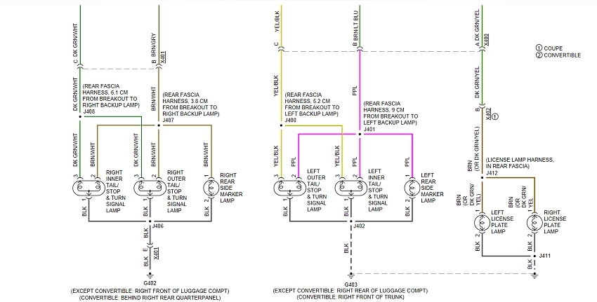
Mini Cooper Tail Light Wiring Diagram Wiring Diagram Schemas
Cooper Motion Sensor Light Switch Wiring Diagram Wiring Schema

Cooper Motion Sensor Light Switch Wiring Diagram Wiring Diagram Schemas
20 Most Recent Cooper Wiring Devices Combination Switch Questions & Answers Fixya

Mini Cooper Tail Light Wiring Diagram Wiring Diagram Schemas
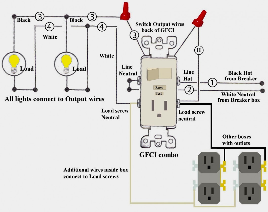
Light Switch To Outlet Wiring Diagram Wiring Diagram
Cooper Motion Light Wiring Diagram Wire Center • throughout God Security Light Wiring Diagram

Mini Cooper Headlight Wiring Diagram DALEACA
How To Wire A Light 3 Way Simple How To Wire, A 3, Light Switch Best Of Cooper Wiring Diagram

Mini Cooper Lighting Diagrams Best Diagram Collection
File Name Cooper Lighting Diagram

2003 Mini Cooper Wiring Diagram Collection
3, Light Switch Wiring Common Most Elegant 4 Switch Wiring Diagram Without Ground Cooper

Cooper Light Switch Wiring Diagram Collection Wiring Diagram Sample
Cooper Light Switch Wiring Diagram WIRGRAM
Mh Ballast Wiring Diagram Cadician's Blog